Reverse engineering an automatic air freshener spray machine

There are lots of commercial electronic products available in the market with simple to intermediate to complex and more complex circuit designs. Now to clarify how they works we have to study the circuit and try to apply our existing knowledge to figure it out, this is generally known as reverse engineering also known as hardware hacking. Practically reverse engineering is a way to progress further and to explore different short techniques which can be very fruitful in our future designs.

In this hack, I tried reverse engineering an automatic air freshener spray machine picked up from the junk. The machine works on two AA batteries i.e on 3 volts. It was not working at first, I unscrewed it and found the the battery connector leads got rusty, cleaned it up but still no response.

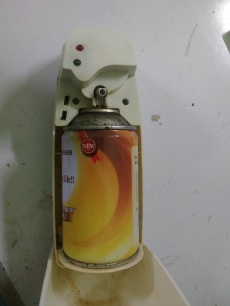
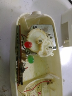
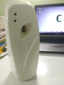
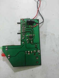
It got a motor gear attachment to increase the torque to press the nozzle of the air freshener can, there are two LEDs and two buttons one is for ON and OFF another is to set the timer which are 9 mins, 18 mins and 36 mins. I took out the circuit and cleaned it with thinner then found that the main problem is in the power input of the PCB, two pads got uprooted causing a discontinuous path to the main circuit so I fixed it and then it respond.

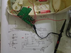
So, the main function of this instruments is to spray the air freshener in the selected time intervals. The green LED blinks in each second 540 times in case of 9 mins interval then the motor is ON for 2 seconds providing enough torque to push the nozzle down and stops then the backward force applied by the nozzle pushes the gear back to the initial position, when the motor is on the red LED turns on. So using my multimeter and oscilloscope I went for a deeper understanding of the behavior of the IC as the manufacturer scratched out the name and part number of the IC. After observing the circuit for half an hour, I made a schematic and as per my assumption it is a 8 pin microcontroller running on 3 volts.

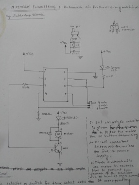
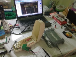
Most of my assumptions matched when I probed the circuit to my oscilloscope. The pin configurations are –

  • Pin 1. Vcc i.e it is connected to +3 volts.
  • Pin 2. This pin is unused in this circuit.
  • Pin 3. Its connected to the base of a NPN transistor having a 100 Ω current limiting resistor in series.
  • Pin 4. It is connected to the delay selection switch and pulled down to ground with a 100 KΩ resistor which provides the delay of 36 mins.
  • Pin 5. It is connected to the 18 mins delay.
  • Pin 6. The green LED is connected in this pin.
  • Pin 7. It is connected to the 9 mins delay.
  • Pin 8. It is the ground pin of the microcontroller.

Observations made :

  1. I probed Pin.3 of the circuit and switched it on and got a pulse which is 2 seconds high that means at starting the motor turns on for 2 seconds.
  2. The delay selector switch pulls the corresponding pins high.
  3.  Pin.6 is programmed like a decade counter the connected green LED blinks in the interval of 1 second in that interval the pin goes low(ground), the current passes through the green LED to ground turning the LED on for one second. And after 1 second it shifts one bit like a decade counter. It covers 12 shifts 9 times for 1 minute. According to my assumption, a counter counts the 12 shifts x 9 and increases its count value correspondingly. Another counter is set to count the minutes, whenever the second counter hits 9 mins. Pin.3 again sends a 2 second high pulse to the motor.

  • The NPN transistor is working as a switch and it delivers the sufficient current needed to drive the motor. A diode is connected in reverse bias in parallel with the motor to protect the transistor from the current peaks formed due to electro magnetic energy stored in the motor coil.
  • The 10uF electrolytic capacitor is connected in parallel with the ON/OFF button to filter the noise due to button debouncing and 0.01uF ceramic disc capacitors filters the noise of the power supply.
Written by : Subhadeep Biswas

Precautions to maintain before using a PC oscilloscope

In every stage of designing a circuit you need an oscilloscope to see whether you are getting the desired output signal or not, and if you are reverse engineering a circuit then oscilloscope is very much essential tool for that. A wide variety of oscilloscopes are available in the market and they are very expensive so most of the hobbyist choose to buy a PC oscilloscope. After some research I bought a cheap one for my basic experiments it’s a Hantek 6022BE, it has 20MHz of bandwidth and 48MSa/s of real time sampling rate. But before using it we have to cope with some problems that can blow this device in seconds.

Here is a awesome video by Dave from EEVBlog on this purpose.

Many of us use a computer SMPS as power supply personally I also use, but when you are probing a circuit with your PC oscilloscope which is powered by the SMPS you need to do a small and simple hardware hack in the power supply. At first there are two sections present in the SMPS, high voltage(HV) side and low voltage(LV) side. HV side and LV side are isolated either by isolation transformer or by opto-couplers.

But in most cases the ground of the LV side is connected with the earthing of the HV side and this is quite dangerous so our hack will be to isolate ground form earthing in HV side.

Now, we have to test the continuity to be sure that ground and earthing of LV side and HV side are connected. Probe the multimeter in the continuity mode if there is no continuity then the HV and LV side is isolated otherwise we have to connect the earth wire of the LV side to the HV side or the circuit

The metallic casing of the SMPS is earthed, so the screw mounts of the LV side needs to be isolated form the LV side circuitry by isolation tape I’ve used thick double sided tape.

From these pictures we can see that the earthing is attached only with the HV side screw terminal which is isolating the the earth and ground and after the hack in working condition a 5V output is tested.

I added a buck converter circuit to +12V output so that I can use it as a variable voltage output between 0-12 volts also drilled the casing and attached banana connectors to make the supply more portable.

Hacked! power supply from old SMPS
Written by : Subhadeep Biswas


Making a simple FM Transmitter

FM Transmitters are that type of gadget which gives you the feelings of a RJ. You can make your own short-range radio channel and air any songs, audio clips as well as your voice in the form of radio frequency. The transmission process is done by following steps which are audio pre amplification followed by modulation then transmission. There are two types of modulation Amplitude Modulation(AM) & Frequency Modulation(FM) both are the part of Radio Frequency (RF). 88 MHz to 180 MHz is generally known as the FM Band.

Audio signal from media player, microphones are very low level signal, of the order of mill volts. This extremely small voltage needs to be first amplified. A common emitter configuration of a bipolar transistor produces an amplified inverted signal.

Another important aspect of this circuit is the oscillator circuit. This is a LC oscillator where energy moves back and forth between the inductor and capacitor forming oscillations. It is mainly used for RF application.

When this oscillator is given a voltage input, the output signal is a mixture of the input signal and the oscillating output signal, producing a modulated signal. In other words, the frequency of the oscillator generated circuit varies with the application of an input signal, producing a frequency modulated signal.

transmitter
A simple Fm Transmitter Circuit

Some details about the design of the circuit :

1.Selecting the Vcc : This circuit uses a NPN Bipolar Junction Transistor (2N3904) or you can use BC547 or equivalent. The Vceo of the transistor is 40V so minimum Vcc is 9V.

2.Selecting the Capacitor C1 : The capacitor modulates the current going through the transistor. A large value indicates bass or low frequency whereas small value indicates treble higher frequency. Here 1uF, 25V electrolytic capacitor is used.

3.Selecting L1 & C4 : Here L1 & C4 is the oscillator known as LC oscillator. Frequency of oscillation is obtained from the formula, f = 1/(2Π√LC). 

Here is some pictures of my complete and decorated setup :

breadboard setup
Breadboard setup
decorated setup1
Decorated setup1
setup2
Complete setup
Written by : Subhadeep Biswas


Hacking the Switched Mode Power Supply

Hacking & something more on the SMPS

The SMPS or the Switched Mode power Supply generally used to drive our Personal Computers. It can also be used to drive other loads also so it is a versatile power supply.

Why SMPS is used in Personal Computers?

In the motherboard of a Personal Computer different sections needs different operating voltages those are +3.3V, +5V, -5V, +12V, -12V DC. The SMPS converts & switches 230V AC supply to those voltages respectively in a very short time so it minimizes the wastage of energy thus the efficiency increases. An ideal SMPS dissipates no power.
introduction
Stages of AC to DC conversion & Switching done in a SMPS:
 
Stages of conversion

Hacking the SMPS & using it as your own power supply

Using the Switched Mode Power Supply as a workbench power supply is not so difficult. Everyone can use it. Starting from beginner level, if you Plug in the SMPS and you will find it is not running. Well that not means that the device is damaged.

Running the SMPS

Step 1: Go for the ATX Power connector. It is the connector having 20 or 24 pins. 
ATX Power connector
Step 2: There is only a green wire(PS_ON). Now short PS_ON with any of the Black wire(COM/Ground) of the SMPS and Plug it again to AC. Now if the SMPS is working the fan will start rotating. Now you are able to use it as your power supply.
 
There is only one green wire(PS_ON) short it with and of the black wire(COM/Ground)
ATX Pin out
Step 3: Now check the voltages of the different pins using a multimeter. 
Reading 1
Reading 2
Reading 3
Step 4: Now use the SMPS as a power supply. I’ve use an old one as my workbench power supply. Here is a simple LED test circuit.
 
Test Circuit
 After this if the SMPS is not starting then you have to attach a dummy load to prevent that. In the casing of the SMPS you will find a chart which describes in which voltage level the current is maximum. If it is 5V then attach a 5Ω 10W resistor between one red wire(5V output) and black wire (ground).
Written by : Subhadeep Biswas