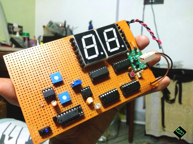
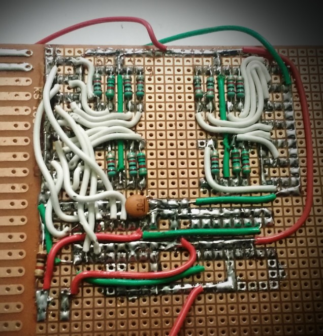
In this project I’ve designed a simple heart beat rate counter using basic building blocks of electronics like timer and counters, OPAMPs etc. My challenge here was to design it without using any microcontroller and to give it a retro look like the 80’s and early 90’s. So I fabricated it on a preff board and soldered the connections using wires.
 The main function of this device is to count pulses form your finger tip for 1 minute. After a minute the 7 segment display will freeze for 10 seconds, the value on the display will be your heart beat rate or BPM. Then by pressing a RESET button all the timer, counters and registers are reset back.
1. heart RATE sensor design
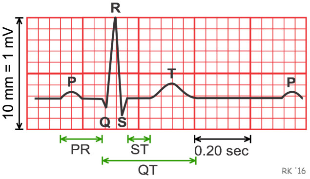
The electrocardiogram is the best way to see the electrical response of our heart whenever it pumps blood. From the graph it can be seen that the R peak is the highest peak of the signal. The counters counts only in the presence of clock signal. CLOCK signals are basically a train of square wave at a certain frequency. So the main objective of the heart rate sensor will be to generate square wave which will be triggered by the R peaks of the signal. My first attempt was to use a contact microphone with an amplifier which will generate the exact response as shown in the image and using a comparator I can easily generate square waves from the R peaks. But keeping the deadline of the project in mind I’ve to change my plan and I decided to use infrared sensor instead. This technique is known as Photoplethysmography where we use a pair of infrared LED and an infrared receiver to generate electrical signals corresponding to the intensity of blood flow through our finger due to the systolic and diastolic pressure.
For the IR transmitter and receiver I am using the TCRT5000 module because the package design is suitable for this project. The image below will show the pin diagram and the most basic interfacing of the TCRT5000 which will output a voltage that can be used for taking ADC readings also.


The receiver of the TCRT5000 is a phototransistor which allows current to flow whenever the base is triggered by the photons emitted by the IR transmitter. To get an output voltage we need to add a resistor which will create a voltage drop across it. Now to get our pulses we need some more add-ons. The circuit below is the actual circuit I used to generate CLOCK pulses for the counter.
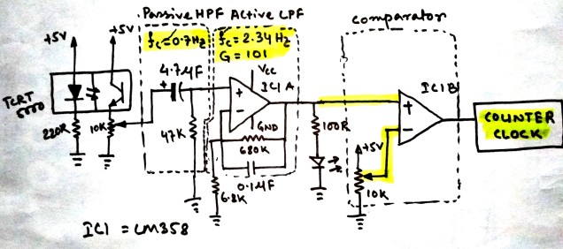
With the following passive high pass filter and active low pass filter it is forming a band pass filter which allows the frequencies between 0.7 Hz to 2.34 Hz that also have a gain of 101. The output LED is to give us visual feedback whenever there is pulses. The output is feed to a comparator circuit which will output the clock pulses for the counters. The 10K trim pot is used to adjust the sensitivity of the comparator.

2. pulse counter and display driver
The CD4026 is the appropriate IC I used for this, it is a counter plus 7 segment decoder in one package. The following circuit diagram will show the connection of the 7 segment displays with the CD4026. 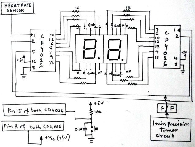
- Pin 1 is the CLOCK pin. The output of the heart rate sensor is attached with it.
- Pin 5 is the CARRY OUT pin so the pin 5 of the first CD4026 is connected with the CLOCK pin of the second CD4026. So that after 9th count the first counter will get reset and start counting from zero but the second counter will count 1 and it will display 10.
- Pin 15 is the RESET pin which resets both the counters whenever the push button is pressed.
- Pin 2 is the Disable CLOCK pin. If it is pulled HIGH then the counter will no longer response to the clock pulses. This pin is connected with a precision 1 min timer which makes the pin HIGH for 10s after 1 min. Thus the display freezes and we get the heart rate.
- Pin 3 is the Display Enable pin which needs to be pulled up to +5V to make the display work.
- Pin 16 is the Vcc pin.
- Pin 8 is the Ground pin.
- The other pins are the output pins which is connected to the segments of the display.
3. precision 1 min timer
This circuit consist of a 555 timer running in astable mode with 50% duty cycle. The frequency of the timer needs to be 1Hz (1/(on time + off time)). The output of the 555 timer is feed to the CLOCK pin of the 1st CD4017 decade counter IC which will shift it’s output every 1s. There are 10 outputs so we are getting a time of 10s now the CARRY OUT pin of the 1st CD4017 is connected to the CLOCK pin of the 2nd CD4017. So after 10s the Q0 pin of the 2nd CD4017 goes HIGH after 20s Q1 pin goes high and so on. So at pin Q5 we will get exactly 60s or 1min and Q5 will be HIGH for 10s. That will activate a flip flop (IC7474) which will then make the CLOCK DISABLE pin of the two CD4026 HIGH for 10s. The circuit diagram for the precision 1 min timer is shown below.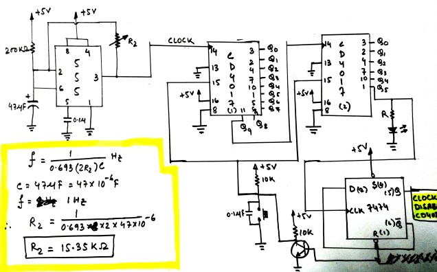

4. power supply
To make it portable I’ve used a 2000mAh cell phone battery with a DC-DC boost converter to provide 5V to the circuit which gives a run time of 7 days in a single charge.
Future modifications : I’m working on a digital stethoscope which will be added in this circuit.
Advantage of using microcontroller : If this project is done using a microcontroller the circuit would be more simple. We don’t have to wait 1 min to get the reading as in the software part we have the freedom of doing calculations. But in this method we will learn the core of digital electronics.
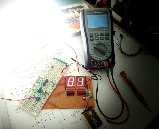
Here is the video demonstration of this project
Written by : Subhadeep Biswas


