There are lots of commercial electronic products available in the market with simple to intermediate to complex and more complex circuit designs. Now to clarify how they works we have to study the circuit and try to apply our existing knowledge to figure it out, this is generally known as reverse engineering also known as hardware hacking. Practically reverse engineering is a way to progress further and to explore different short techniques which can be very fruitful in our future designs.
In this hack, I tried reverse engineering an automatic air freshener spray machine picked up from the junk. The machine works on two AA batteries i.e on 3 volts. It was not working at first, I unscrewed it and found the the battery connector leads got rusty, cleaned it up but still no response.
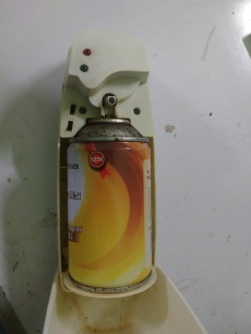
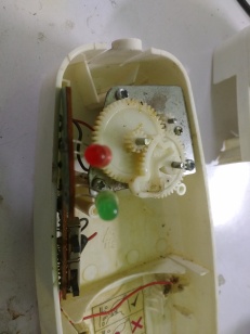
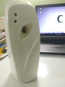
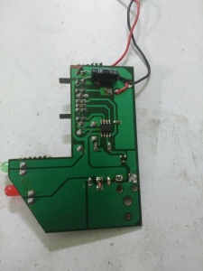
It got a motor gear attachment to increase the torque to press the nozzle of the air freshener can, there are two LEDs and two buttons one is for ON and OFF another is to set the timer which are 9 mins, 18 mins and 36 mins. I took out the circuit and cleaned it with thinner then found that the main problem is in the power input of the PCB, two pads got uprooted causing a discontinuous path to the main circuit so I fixed it and then it respond.
So, the main function of this instruments is to spray the air freshener in the selected time intervals. The green LED blinks in each second 540 times in case of 9 mins interval then the motor is ON for 2 seconds providing enough torque to push the nozzle down and stops then the backward force applied by the nozzle pushes the gear back to the initial position, when the motor is on the red LED turns on. So using my multimeter and oscilloscope I went for a deeper understanding of the behavior of the IC as the manufacturer scratched out the name and part number of the IC. After observing the circuit for half an hour, I made a schematic and as per my assumption it is a 8 pin microcontroller running on 3 volts.
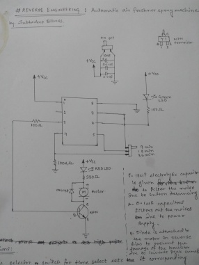
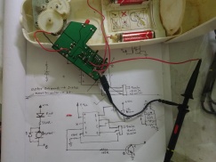
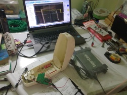
Most of my assumptions matched when I probed the circuit to my oscilloscope. The pin configurations are –
- Pin 1. Vcc i.e it is connected to +3 volts.
- Pin 2. This pin is unused in this circuit.
- Pin 3. Its connected to the base of a NPN transistor having a 100 Ω current limiting resistor in series.
- Pin 4. It is connected to the delay selection switch and pulled down to ground with a 100 KΩ resistor which provides the delay of 36 mins.
- Pin 5. It is connected to the 18 mins delay.
- Pin 6. The green LED is connected in this pin.
- Pin 7. It is connected to the 9 mins delay.
- Pin 8. It is the ground pin of the microcontroller.
Observations made :
- I probed Pin.3 of the circuit and switched it on and got a pulse which is 2 seconds high that means at starting the motor turns on for 2 seconds.
- The delay selector switch pulls the corresponding pins high.
- Pin.6 is programmed like a decade counter the connected green LED blinks in the interval of 1 second in that interval the pin goes low(ground), the current passes through the green LED to ground turning the LED on for one second. And after 1 second it shifts one bit like a decade counter. It covers 12 shifts 9 times for 1 minute. According to my assumption, a counter counts the 12 shifts x 9 and increases its count value correspondingly. Another counter is set to count the minutes, whenever the second counter hits 9 mins. Pin.3 again sends a 2 second high pulse to the motor.

- The NPN transistor is working as a switch and it delivers the sufficient current needed to drive the motor. A diode is connected in reverse bias in parallel with the motor to protect the transistor from the current peaks formed due to electro magnetic energy stored in the motor coil.
- The 10uF electrolytic capacitor is connected in parallel with the ON/OFF button to filter the noise due to button debouncing and 0.01uF ceramic disc capacitors filters the noise of the power supply.
Written by : Subhadeep Biswas
Great job. I have a similar one and was wondering: would it be possible to increase the delay to more than 36 minutes?
LikeLiked by 1 person
Yes, it needs to be programmed to count more pulses
LikeLike
hi brothr..wonderful observation…during lockdown i had also done the same project without any instruments help..I Carefully desoldered that IC and i maufactured a timer sensing circuit…I need more IC…can you help me in this/..I will give you payment..pin me @9656525700 whatsaapp
LikeLiked by 2 people
Hi,
I want to develop this product on commercial scale can you help me I’ll pay you for this ?
LikeLiked by 1 person
You have shown wrong connection of + and _ supply of power to pin 1 and 8. Please check it
LikeLike
You have shown wrong connection of power supply positive to 555 ic pin 1 and negative to pin 8 it is very wrong.
LikeLike
Hi, please read it carefully. It is not a 555 timer IC, the IC is not verified as the manufacturer etched the part number of the IC. So the diagram is made by reverse drawing the traces.
According to my assumption, it is a low-cost microcontroller.
LikeLike
The vcc and gnd connections are wrongly shown
LikeLike