What is an “OPAMP”?
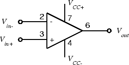
An operational amplifier (or an op-amp) is an integrated circuit (IC) that operates as a voltage amplifier. An op-amp has a differential input. That is, it has two inputs of opposite polarity. An op-amp has a single output and a very high gain, which means that the output signal is much higher than input signal.
Vout = AOL[(V+) – (V-)],
Where AOL = Open loop gain of opamp
Ideal characteristics of a OPAMP:
1. Opamp has high input impedance & low output impedance.
2. Zero common mode gain or infinite common mode rejection.
3. Infinite open loop gain AOL.
4. Infinite bandwidth.
** opamp is used as differentiator, integrator, comparator, current – voltage converter, voltage- current converter, etc.
Parts List for the circuit :
1. IC LM35, Opamp (LM741)
2. Resistance- 10K, 470 ohms(2), 2K pot.
3. LED (red, green)
4. Wires
5. Bread board
6. Digital Multimeter
7. 12 v Battery
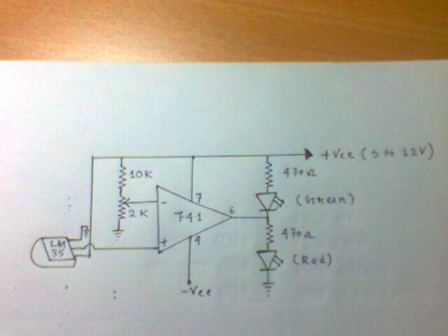
“HERE IN THIS PROJECT WE USE OPAMP AS A COMPARATOR”

Theory: This project uses IC LM35 as a sensor for detecting accurate centigrade temperature. Linearity defines how well over a range of temperature a sensor’s output consistently changes. Unlike thermistor, linearity of a precision IC Sensors are very good of 0.5°C accuracy and has wide temperature range. It’s output voltage is linearly proportional to the Celsius (Centigrade) temperature.
The LM35 is rated to operate over a -55° to +150°C temperature range. It draws only 60 µA from its supply, it has very low self-heating, less than 0.1 °C in still air. LM35 Operates from 4 to 30 volts. Output of IC is 10mv/degree centigrade. For example if the output of sensor is 280 mV then temperature is 28 °C. So by using a Digital multimeter we can easily calculate the degree temperature. For trigger point you should set the voltage of pin 2 of IC 741 by using preset or potentiometer. Our aim of this project is not to construct a thermometer but to activate or deactivate a device at a particular margin temperature. For simplicity we have used 2 LEDs for indication of both low (Green) and high (Red) temperature.
Working principle: The output of IC2(LM35) increases in proportional to the temperature by 10 mV/°C , this varying voltage is feed to a comparator configuration of IC 741 (OP Amplifier). At first we set sensitivity (set a voltage by varying the 2KΩ pot) at pin no.2 . If we consider that the sensitivity voltage as V1 & The output of LM35 (pin no. 3) as V2, then we can describe easily that what is happening. If voltage V1> V2 ,then the output of the comparator at +Vsaturation , then the green LED is on and the red LED is off. When the temperature increases that the output of LM35 is also increases, after a certain time when voltage V2 cross the voltage V1 then the output of the comparator at –Vsaturation , then the red LED is on and green LED if off. When V1=V2 then the output is 0 and two LED is in off state. We have used IC741 as a non-inverting amplifier. As a comparator the output voltages will be
Vout = +Vsat when V1>V2
= -Vsat when V1<V2
= 0 when V1 = V2

Written by : Sourav Tamli

