Light Dependent Resistor or LDR :
The LDR is also known as the Photo-resistor or Photo-cell, a light controlled variable resistance which exhibits photo conductivity. Ideally it behaves as a wire having a zero resistance when the incident light intensity increases as well as much higher resistance value when the intensity decreases. So, we can say that under bright light, resistance is very low & in darkness resistance is very high or infinite ideally.

This image shows how LDR looks like. There are different sizes available in the market. It is made of a high resistance semiconductor. The red track on the LDR is a layer of Cadmium Sulphide (CdS). Practically LDRs are not polarized.
Area of Application :
There are a large numbers of applications that can be done by using LDRs such as an automatic street light which turns on itself when the sun sets, a morning alarm which senses the morning light and initiate the alarm, many security applications like the laser alarm, it can also be applied as solar tracker, a line follower robot also uses a LDR to sense the black line etc.
Following images will describe the variance of Resistance as well as the circuit symbol & some test result:


–The most simple circuit that you can do using a LDR–

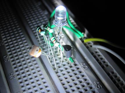
This simple circuit is the primary stage of LDRs applications later it can be modified as a automatic street light. When LDR is uncovered then LED is in OFF state and when covered LED is in ON state. So it may be a perfect system for street lighting. Here the BC547 transistor is working as a switch. So the results are quite satisfactory…


So, this is how we can use LDR in a circuit. Also we can construct sensors as a physical parameter (light) is being converted to resistance value.
Written by : Subhadeep Biswas
What is the working principle?…why is the 1.2k ohm resistor needed?
LikeLike
1.2K ohm needed just to limit the base current so that the transistor doesn’t get damaged.
But in this case 10K Ohm is doing the same so 1.2K is for precaution.
Here 10K and the LDR providing the signal. Base to emitter voltage or Vbe is +0.7 V
If Vbe > 0.7 V transistor is in saturation region(i.e base-emitter is forward biased & collector current is maximum) & if < 0.7 V it will be in cut-off region(i.e base-emitter is reversed biased & collector current is 0). So here Vbe is adjusted using combination of 10K and the LDR in which LDR varies with the intensity of light.
LikeLike